Jul 30, 2024
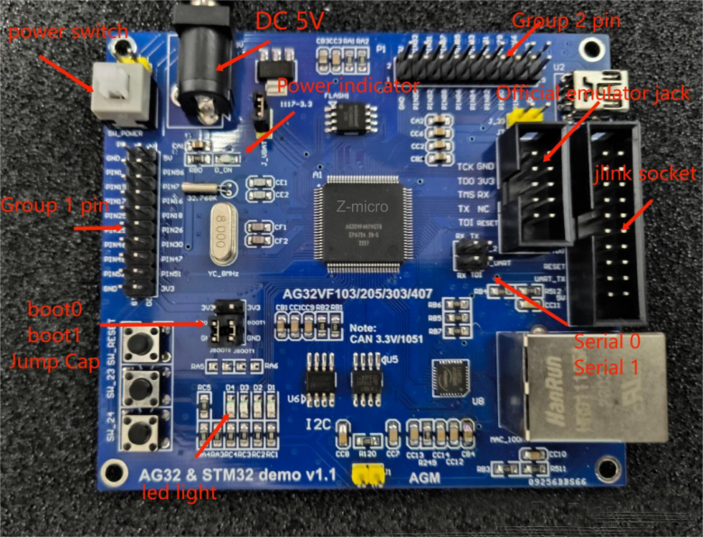
Before using the development board, make sure that the development environment has been installed.
Installation environment process, please refer to the document "AG32 development environment setup.pdf".
I. Power up:
Supply 5V power to the development board, turn on the switch, you can see the small red light next to the power supply is on.
Use the example routine:
Open the example routine, under the SDK path:
D:xxxxxAgRV_pioplatformsAgRVexamplesexample (note the double example here)
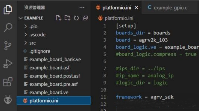
Since the board uses the 407 chip, you need to modify the board type in platformio.ini first:
board = agrv2k_103
Modified to:
board = agrv2k_407
For simplicity in verification, you can start by temporarily removing the configuration from example_board.ve, leaving only the first two:
SYSCLK 100
HSECLK 8
III. Burn VE file and code bin:
Connecting the dots:
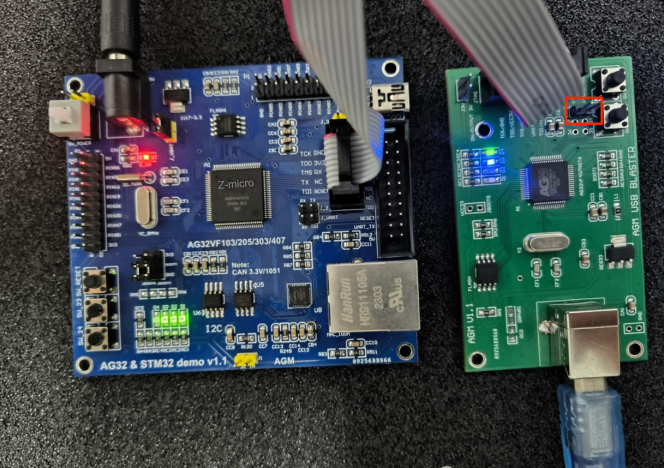
The red box is connected with a jump cap by default, you need to pull out the jump cap to adjust to the CMSIS-DAP mode, the use of AGM_BLASTER burner needs to be in accordance with the driver first, the installation of see " AGM_BLASTER .pdf".
Configuration:
Verify that the following two lines in platformio.ini are turned on debug_tool = cmsis-dap-openocd
upload_protocol = cmsis-dap-openocd

With the official burner, the PC is driver free.
Burning:
When you use a new board for the first time, you have to burn the VE configuration first. (If you burn the program bin without burning the VE, you will get an error) Burn the VE:
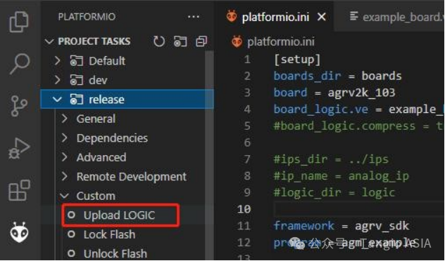
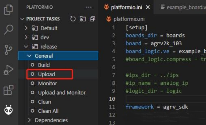
Burning program:
Simulation:
Click on the Simulation button to enter the simulation debugging. It can be run in a single step to the end of the main function.
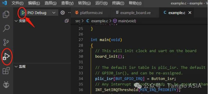
The single-step state is shown in the figure:
Fourth, check the led lights:
In the main function of the example program, the last function is a call to TestGpio().
Inside the TestGpio() function, there is a blinking operation for the LEDs.
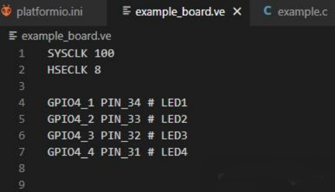
Since we deleted all the IO configurations in example_board.ve in step 3, we will now restore the pin mapping of the led. Now restore the pin mapping of the led. copy the following settings to the ve file:
GPIO4_1 PIN_34 # LED1
GPIO4_2 PIN_33 # LED2
GPIO4_3 PIN_32 # LED3
GPIO4_4 PIN_31 # LED4
The result after copying is shown below:

At this point, burn the ve file again.
(burn VEs as in step 3 above)
After successful burning, you can see several led's in the lower left corner blinking.
